MD02 · RS-485 sensor
Generic OEM — air temperature & humidity
XY-MD02
Air temperature + relative humidity transmitter. ASCII protocol on the bench-tested revision.
Bus & electrical specs
Specs sourced from: XY-MD01/MD02 family datasheet + Sankhya v4 node bench test.
This unit speaks ASCII, not Modbus
The revision Sankhya bench-tested is not a Modbus-RTU slave. A full Modbus scan (6 baud rates, 8N1/8E1/8O1, function codes 0x03/0x04, several register starts) returned zero valid responses. Instead it answers a bare four-byte ASCII command with a plain-text string — no CRC, no register map.
Response format <temperature>C,<relative_humidity>%, parsed with ^(-?\d+(?:\.\d+)?)C,(\d+(?:\.\d+)?)%$:
| Field | Type | Unit | Capture |
|---|---|---|---|
| air_temperature | float | °C | group 1 |
| relative_humidity | float | %RH | group 2 |
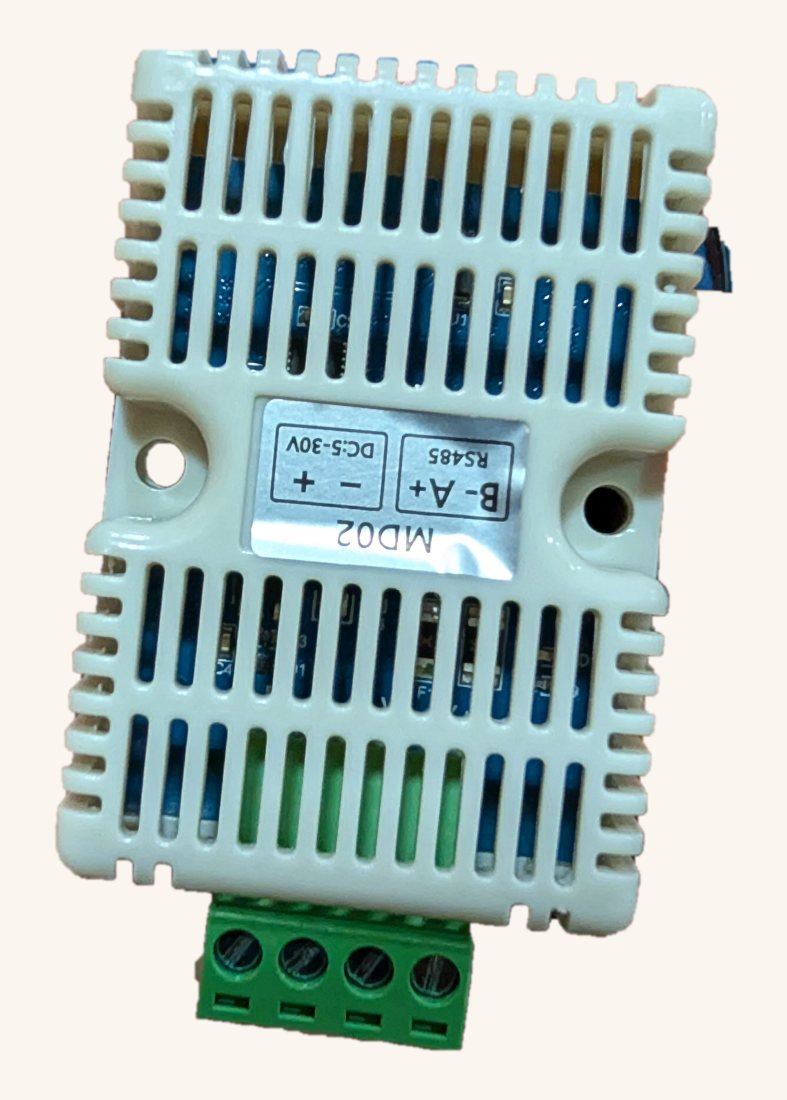
Factory label is upside-down
The printed sticker contradicts the PCB silkscreen
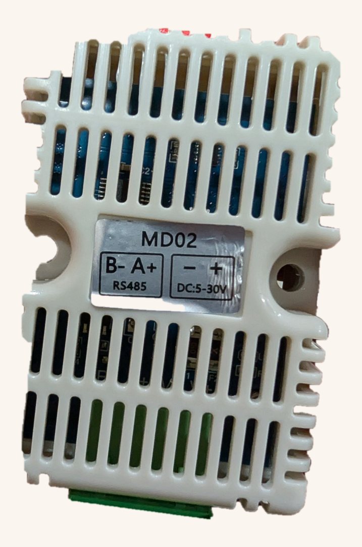
On the XY-MD02 units we received, the adhesive label on the vented cap is rotated 180° relative to the board's own silkscreen. Wire by the sticker as printed and you swap the RS-485 data pair with the power pair — feeding DC into the data lines and the bus signal into the supply pins. Best case the sensor never answers; worst case you damage it.
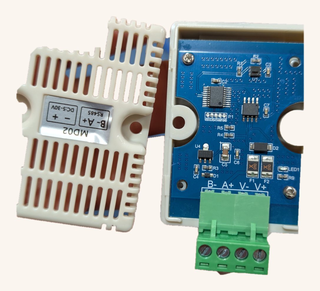
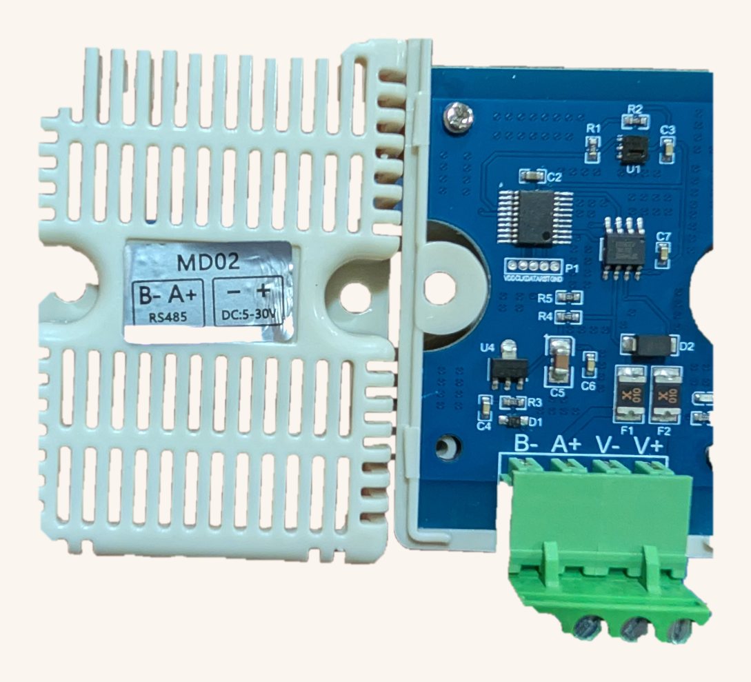
The PCB silkscreen is the authority. Open the cap once and confirm against the board. Looking at the terminal block with the four screws toward you, the correct order is:
Either re-apply the label the right way up (steps below) or ignore the sticker entirely and wire to the silkscreen. The data terminals are marked B− / A+ — pair them to your bus B / A respectively.
The problem · what's wrong
The fix · how to correct it
Documented from physical units, Sankhya field bench, June 2026. Your unit's revision may differ — always verify against its own silkscreen.
Notes & caveats
Directly confirmed on a Sankhya v4 node. The bare four-byte ASCII command READ at 9600 8N1 returned 16.02C,55.85%. This exact revision should use XY_MD02_ASCII_READ, not a Modbus register-map profile. It can coexist with 4800-baud Modbus sensors on the same physical RS485 bus by switching UART baud/protocol between polls.
Common questions
- What baud rate does the XY-MD02 use by default?
- 9600 bps, 8N1. It is an ASCII device, not Modbus.
- What supply voltage does the XY-MD02 need?
- DC 5–30 V (< 0.2 W).
- Is the XY-MD02 compatible with the Sankhya platform?
- Yes — it is in the Sankhya RS-485 sensor library and the firmware-generation pipeline can produce node firmware for it.
Run this sensor on a Sankhya node
Every sensor on this page is in our RS-485 library. Pick your model, and the firmware-generation pipeline builds the Modbus (or ASCII) polling code for an ESP32-S3 node — no hand-coding the register math.
Contact Us